How to Size Off-Grid Solar Power for CCTV in the Philippines
Calculate the right off-grid solar power system for CCTV cameras using daily load, sunlight, battery autonomy, losses and future expansion.
By Maxsol Team

An off-grid solar power system for CCTV cameras should be sized from the site’s total daily energy use in watt-hours (Wh), not from the camera count alone. Add every device that runs on the system, allow for conversion and charging losses, then select enough solar generation and battery storage for the site’s expected weather and required backup period.
For Philippine installations, this matters especially during extended cloudy or rainy periods. A system that appears adequate on a bright day may struggle if the panel is shaded, the camera has infrared night vision, or the battery must cover several low-sun days.
Inventory the full site load
Start with an equipment list. Include every item drawing power from the solar system, whether it is mounted at the camera pole, inside an outdoor enclosure, or located at a nearby monitoring point.
A typical solar CCTV site may include:
- Fixed, PTZ, or thermal cameras
- Camera infrared LEDs or white-light illuminators
- PoE switch, PoE injector, or DC distribution equipment
- Wireless bridge, CPE, router, or mobile data device
- NVR, edge recorder, SSD, or network storage device
- Alarm, speaker, access-control device, or environmental sensor
- Cooling fan, cabinet light, display, or other auxiliary load
- DC-to-DC converters, voltage reducers, or inverter loads
Use each device’s actual operating wattage where possible. A power adapter label states its maximum output capability, which may be much higher than normal consumption. Product datasheets, measured current draw, and controlled site testing are better inputs.
Account for day and night consumption
Many cameras consume more power after dark. Infrared LEDs, heaters, wipers, PTZ movement, and onboard analytics can materially change daily consumption.
For every load, note:
- Running power in watts (W)
- Operating hours per day
- Higher-power modes, such as IR operation
- Whether it runs 24/7 or only at scheduled times
For a camera with different daytime and nighttime loads, calculate each period separately:
Daily energy (Wh) = daytime watts × daytime hours + nighttime watts × nighttime hours
For example, a camera using 6W for 12 daylight hours and 10W for 12 night hours consumes:
(6W × 12h) + (10W × 12h) = 192Wh per day
Do not overlook network equipment. A PoE switch must power itself as well as connected cameras. Likewise, a wireless bridge can be a continuous load even when cameras are idle.
Convert load into daily energy
Once the list is complete, convert every load into watt-hours per day and add the results.
Daily energy (Wh/day) = device power (W) × operating time (hours/day)
Here is an illustrative load calculation for a small remote CCTV point:
| Device | Estimated operating load | Operating time | Daily energy |
|---|---|---|---|
| Two cameras | 14W combined average | 24 hours | 336Wh |
| PoE switch or injectors | 8W | 24 hours | 192Wh |
| Wireless bridge | 5W | 24 hours | 120Wh |
| Edge recorder | 8W | 24 hours | 192Wh |
| Total device energy | 840Wh/day |
This is only an example. The actual consumption of your camera, PoE equipment, recorder, and wireless link may be substantially different.
Add system losses before selecting equipment
The load total is not the same as the energy that must come from the battery and solar panel. Energy is lost in cable runs, PoE delivery, voltage conversion, charge control, and battery charging.
For early planning, apply a loss allowance to the device total:
Design daily energy = total device energy ÷ system efficiency
If the estimated device load is 840Wh/day and the overall delivery efficiency is assumed at 85%:
840Wh ÷ 0.85 = about 988Wh/day
This design figure gives more realistic room for system losses. Confirm actual conversion efficiencies, cable lengths, and voltage-drop limits during final design.
Avoid simply adding a fixed number of watts “for safety”. A percentage allowance tied to the site load is clearer and scales properly as cameras or network devices are added.
Account for solar resource and losses
The solar panel must collect enough energy to run the load and restore the battery. Panel wattage alone does not indicate daily solar output because sunlight varies by season, site orientation, weather, shading, and cleanliness.
Use peak sun hours (PSH) for the actual installation area. Peak sun hours are not the number of daylight hours. They represent the daily solar energy equivalent of full-strength sunlight.
A practical solar-array estimate is:
Required panel watts = design daily energy ÷ (peak sun hours × solar collection factor)
The solar collection factor allows for real-world effects such as:
- Panel temperature
- Dirt, salt residue, leaves, and bird droppings
- Charge-controller and wiring losses
- Non-ideal tilt and orientation
- Short-term cloud cover
- Panel ageing
- Partial shading from trees, buildings, poles, or antenna structures
Work from conservative solar conditions
In the Philippines, a design should not rely only on the clearest-season solar conditions. Wet-season cloud cover, typhoon-related weather, and changing shade patterns can reduce useful collection significantly.
Use the lower solar-resource period relevant to the project, particularly where uninterrupted surveillance is important. If site data is unavailable, treat initial calculations as preliminary and leave room for adjustment after a site survey.
Even a small amount of shade can have an outsized effect on solar charging. Check for shade throughout the day, not only at installation time. A new building, growing tree canopy, elevated signboard, or telecom antenna can later reduce production.
Check panel and battery balance together
A large battery can keep cameras running for a while, but it cannot solve a persistent solar-energy shortfall. Similarly, a large panel cannot maintain service through the night without adequate battery storage.
For example, if the design energy is 988Wh/day and the site is planned around 4 peak sun hours with a 75% solar collection factor:
988Wh ÷ (4 × 0.75) = about 329W of panel capacity
This calculation shows why a 200W panel should not automatically be assumed sufficient for an approximately 1kWh/day CCTV load. The correct outcome depends on the site’s actual solar resource, load profile, losses, and backup requirement.
Choose battery autonomy
Battery autonomy is the period the system should operate with little or no useful solar charging. It is usually expressed in days.
For CCTV, autonomy should reflect the consequence of losing surveillance:
- Low-risk or easily serviced sites: shorter autonomy may be acceptable.
- Remote sites or sites with difficult access: allow more reserve.
- Security-critical locations: design for the expected worst low-sun period, not only overnight operation.
- Monsoon-exposed locations: evaluate cloudy-day performance carefully.
A battery-capacity estimate can be calculated as:
Required nominal battery Wh = design daily energy × autonomy days ÷ usable battery fraction
The usable battery fraction should account for the chosen maximum depth of discharge and delivery losses. Do not assume the entire nominal battery capacity is available for continuous field use. Battery protection settings, temperature, battery condition, and connected equipment all affect usable energy.
Example battery calculation
Using the earlier 988Wh/day design energy figure, one day of autonomy and an assumed 80% usable battery fraction would require:
988Wh × 1 day ÷ 0.80 = about 1,235Wh nominal battery capacity
For two days of autonomy:
988Wh × 2 ÷ 0.80 = about 2,470Wh nominal battery capacity
This example illustrates an important point: a battery that supports one night may not provide enough reserve for one or two cloudy days. It also does not confirm compatibility with any particular kit, because camera voltage, output type, peak current, charging conditions, and site loads must still be checked.
Consider peak power as well as watt-hours
Battery Wh capacity determines how long the system may run. It does not by itself confirm whether the system can support peak demand.
Check:
- Camera start-up and PTZ movement current
- Simultaneous IR or white-light activation
- PoE switch power budget
- NVR drive start-up demand
- Radio transmit peaks
- Maximum current of each DC output
- Inverter surge demand, if an AC device is used
A system can have enough stored energy on paper but still shut down if an output, fuse, cable, or converter is undersized for peak current.
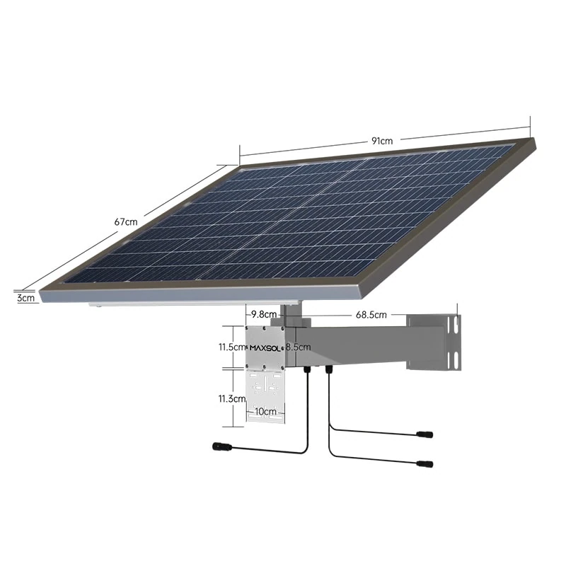
Compare approved 192Wh to 1280Wh kits
The following Maxsol systems provide documented examples at different panel and battery capacities. Treat them as starting points for comparison, not as runtime guarantees for an unspecified CCTV load, weather pattern, or installation environment.
| System | Documented solar configuration | Documented battery capacity | What to verify for CCTV sizing |
|---|---|---|---|
| CS3015 30W solar system with 192Wh battery | 30W monocrystalline panel | 12.8V 15Ah, 192Wh LiFePO4 | The CS3015 includes an MPPT controller and three DC12V output ports. Confirm the camera voltage, combined output current, daily load, and reserve requirement. |
| CS6030 60W solar system with 384Wh battery | 60W panel | 12.8V 30Ah, 384Wh | Compare the 384Wh nominal capacity and 60W panel against calculated daily energy, low-sun performance, and required outputs. |
| CS12060 120W solar system with 768Wh battery | 120W panel | 12.8V 60Ah, 768Wh | Assess whether both the larger battery reserve and panel collection estimate meet the site’s actual load and autonomy target. |
| CS200100 200W solar system with 1280Wh battery | 200W system configuration | 12.8V 100Ah, 1280Wh | Use the 1280Wh nominal battery figure and 200W configuration as inputs to the battery and panel calculations; do not assume a fixed camera runtime. |
The listed battery capacities are nominal energy figures. Available energy in use will be lower after allowing for battery protection limits, cable and conversion losses, and operating conditions.
The CS3015’s documented three DC12V output ports may be relevant for a small 12V DC camera setup. However, output connectors and power requirements must be checked against the specific cameras, PoE equipment, and any required converters. Do not assume that a system intended for DC devices will directly power a PoE camera or AC recorder without suitable, correctly sized equipment.
Validate before purchase
Before selecting an off-grid solar power system for CCTV cameras, validate the full design with a site-specific checklist.
Electrical and network checks
- Record the rated and measured operating watts of each camera and network device.
- Separate day and night camera consumption.
- Confirm the PoE voltage, PoE standard, switch power budget, and per-port power demand where PoE is used.
- Confirm whether devices require 12V DC, another DC voltage, PoE, or AC power.
- Check peak current, connector type, polarity, fusing, and cable gauge.
- Allow for voltage drop on long DC and PoE cable runs.
- Include the power draw of recorders, wireless links, routers, and any future peripherals.
Solar and physical-site checks
- Identify shade at different times of day and across seasons.
- Use solar-resource assumptions appropriate to the installation area and lower-sun periods.
- Plan panel mounting for secure support, drainage, wind exposure, and practical cleaning access.
- Protect outdoor cable entries, connectors, and enclosures from water ingress.
- Consider heat inside cabinets, particularly where a recorder, PoE switch, and battery share an enclosure.
- Review lightning and surge protection requirements for exposed camera poles, panel frames, network cables, and power lines.
- Ensure the solar equipment, battery, cameras, and wireless devices can be safely maintained at the installed height and location.
Allow for expansion
A CCTV site often grows after commissioning. One additional camera can increase not only camera consumption but also PoE demand, storage requirements, wireless traffic, and nighttime load.
Build expansion into the calculation where practical. A reasonable design margin is more useful than guessing at a much larger system, because the final solution must still match the required voltage, output arrangement, panel space, and mounting constraints.
Common sizing mistakes to avoid
The most common error is choosing a solar kit based on the number of cameras rather than measured daily watt-hours. Two cameras may draw very little or consume substantial energy depending on resolution, night lighting, PTZ use, PoE equipment, and recording arrangement.
Other frequent mistakes include:
- Counting only camera power and excluding the switch, bridge, and recorder
- Using daylight hours instead of peak sun hours
- Ignoring charging, conversion, and cable losses
- Selecting battery capacity for one night but not for cloudy-day autonomy
- Assuming a panel’s watt rating equals its actual daily energy harvest
- Sizing only for average load while ignoring night-mode and peak power
- Mounting panels where seasonal shading will occur
- Adding an inverter for a small AC load without accounting for its standby consumption and losses
- Adding cameras later without recalculating the battery and solar requirement
FAQ
How many CCTV cameras can a solar power system run?
There is no fixed camera count. Calculate the total watt-hours used by the cameras and supporting equipment, then compare this with expected solar collection and usable battery energy. A low-power fixed camera and a PTZ camera with illuminators can have very different daily consumption.
Is battery size or solar-panel size more important?
Both must be sufficient. The battery provides overnight and cloudy-day reserve, while the solar panel must replace the energy used each day. Oversizing only one side can leave the system unable to recharge or unable to operate through low-sun periods.
Can I use a solar CCTV system for PoE cameras?
Possibly, but the solar system must support the required power architecture. Confirm the DC output, voltage conversion requirements, PoE switch or injector input, total PoE budget, cable distance, and peak demand. Do not rely only on battery Wh capacity.
Should I include an NVR in the solar calculation?
Yes, if it is powered from the same system. Recorders can be a significant 24/7 load, especially when fitted with storage drives. Where practical, compare the energy impact of local recording, edge storage, and a separate powered monitoring location.
A reliable solar CCTV design begins with a complete load sheet and conservative site assumptions. Before purchase, compare the linked Maxsol models against your port count, load, cable distance, power type, weather exposure, environment, and management requirements.