12V vs 24V vs 48V DC Power for Outdoor PoE
Compare 12V, 24V and 48V outdoor PoE DC power for voltage range, cable loss, startup sag, protection and commissioning at solar CCTV sites.
By Maxsol Team

For most outdoor PoE networks, 24V is a practical distribution voltage for moderate loads and cable distances, while 48V generally reduces cable loss and voltage sag on longer or higher-power runs. A 12V system can work for short, low-power branches, but its higher current makes cable sizing, connector condition and startup voltage more critical.
The right choice in a 12V vs 24V vs 48V outdoor PoE DC power design is not based on nominal voltage alone. Check the complete operating range of the battery, controller, switch, converter and connected devices; calculate round-trip cable loss; protect each branch; and confirm performance through loaded commissioning measurements.
| DC distribution option | Where it can fit | Main advantage | Main limitation |
|---|---|---|---|
| 12V nominal | Short branches, low-power equipment and systems already based on a 12.8V battery | Simple integration with some battery-powered equipment | Highest current and cable loss for the same power |
| 24V nominal | Moderate loads, compact solar sites and equipment designed for a 24V-class input | Useful balance between current, conversion and component selection | Still requires conversion where the PoE output or load needs another voltage |
| 48V nominal | Longer cable runs and higher aggregate loads | Lowest current and voltage drop for the same delivered power | Battery and converter limits, touch-safe work practices and PoE compatibility still require verification |
A 48V distribution bus is not automatically IEEE-compliant PoE. Distribution voltage, PoE output voltage, pinout, polarity and powered-device detection are separate compatibility questions.
Map sources, loads and operating voltage ranges
Begin with a one-line power diagram rather than selecting a voltage from the battery label. Map every conversion and cable section:
Solar panel → charge controller → battery → branch protection → DC cable → converter or PoE switch → Ethernet cable → camera, radio or access point
For each block, record:
- Nominal input and output voltage
- Minimum and maximum operating voltage
- Startup or inrush current
- Continuous and peak power
- Conversion efficiency across the expected load range
- Low-voltage shutdown and recovery thresholds
- Cable length, conductor resistance and connector count
- Ambient and enclosure temperature limits
- Required polarity, pinout and communications protocol
Nominal voltage is only a category. A battery described as 12V, 24V or 48V operates across a range that changes with chemistry, charge state, load, temperature and controller behaviour. The input range of every connected device must cover the actual source range after cable loss and transient sag.
For example, the Maxsol CS12060 solar power system documents a 120W monocrystalline panel, a 12.8V 60Ah 768Wh LiFePO4 battery, an MPPT controller and three DC12V outputs, with RS485 as an option. These are nominal product details, not evidence that every 12V network device can be connected directly. Confirm the current controller limits, battery charging temperatures, branch ratings and equipment input ranges before specification.
The stated 768Wh is nominal stored energy, not usable energy delivered to cameras. Controller losses, converters, cable losses, battery protection thresholds, operating temperature and reserve requirements all reduce usable output. For a focused overview of the chemistry, see the guide to LiFePO4 battery considerations for solar CCTV.
Keep the DC bus and PoE output separate
A system may use a 12V or 24V battery bus while delivering a different voltage to the PoE ports. That conversion stage must be sized for both total power and the behaviour of each load.
The Maxsol IOT2802SFG-S managed solar industrial PoE switch documents eight Gigabit PoE ports, two SFP ports, a 120W PoE budget, 90W BT support, PV and battery monitoring, and configurable 24V or 48V PoE on ports 3 and 4. Its documented PV and battery input is DC22–29.2V. Verify actual port allocation, charging limits, battery compatibility and the supplied configuration.
In particular, a 12.8V battery kit is not a direct compatible input for a device requiring DC22–29.2V. The linked products should therefore be treated as separate selection examples, not as a tested compatible bundle.
Total switch budget is also not enough on its own. Check the per-port limit, simultaneous loading, cable loss and camera startup behaviour. The separate guide on calculating a PoE power budget for security cameras explains that layer in more detail.
Allow for startup sag and converter limits
Outdoor surveillance loads do not always draw steady current. Cameras may use more power while booting, switching infrared illumination, operating a heater, moving a pan-tilt-zoom mechanism or enabling other accessories. Wireless radios and switches can also produce short startup peaks.
During these events, voltage at the equipment may fall because of:
- Battery internal resistance
- A low battery state of charge
- Controller current limiting
- Undersized conductors
- Long DC cable runs
- Corroded or loose terminals
- Fuse and disconnect resistance
- Converter current limits
- Several devices starting at the same time
A system can therefore pass a no-load voltage check and still restart repeatedly at night.
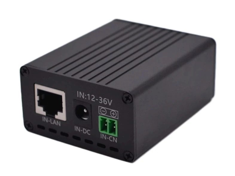
When assessing a converter, do not assume that its highest advertised voltage and power are available together. The Maxsol POE24V DC-to-PoE converter accepts 12–36V DC and provides an adjustable 12–57V PoE output, Gigabit Ethernet and an LCD voltage display. Its documented continuous load when converting 12V to 48V is at most 30W. Up to 94% conversion efficiency is a maximum figure, not a guaranteed design value at every input voltage and load.
IEEE powered-device detection or negotiation is not established by those product facts. Before connecting a camera, radio or access point, verify:
- Active or passive PoE requirements
- Output voltage range
- Polarity and Ethernet pinout
- Maximum continuous and startup load
- Input current at the lowest expected source voltage
- Converter thermal derating
- Behaviour during overload and low-voltage recovery
Use the lowest expected converter efficiency—not the published maximum—when establishing a conservative design budget. If no full efficiency curve is available, leave additional margin and validate the assembled system under load.
Calculate round-trip cable voltage drop
DC voltage-drop calculations must use the full current path. If equipment is 30 metres from the battery, the electrical path is approximately 60 metres because current travels to the load and returns through another conductor.
The basic method is:
Round-trip resistance = conductor resistance per metre × one-way distance × 2
Voltage drop = current × round-trip resistance
Cable power loss = current² × round-trip resistance
Current should be calculated at the DC distribution voltage, including conversion losses:
Input current = load power ÷ (distribution voltage × assumed conversion efficiency)
Hypothetical voltage-drop example
The following figures are illustrative assumptions only. They are not measured Maxsol product performance and are not a cable recommendation.
Assume:
- Load output: 48W
- Assumed conversion efficiency: 90%
- Required converter input power: 48W ÷ 0.90 = 53.3W
- One-way DC cable length: 30m
- Assumed conductor resistance: 0.007Ω per metre per conductor
- Round-trip length: 60m
- Round-trip resistance: 60m × 0.007Ω/m = 0.42Ω
- No connector, fuse or temperature correction is included
| Nominal bus | Calculated current | Cable voltage drop | Drop as percentage of nominal voltage | Cable power loss |
|---|---|---|---|---|
| 12V | 4.44A | 1.87V | 15.6% | 8.28W |
| 24V | 2.22A | 0.93V | 3.9% | 2.07W |
| 48V | 1.11A | 0.47V | 1.0% | 0.52W |
This example demonstrates why higher-voltage distribution is attractive for long outdoor runs. Doubling the voltage approximately halves the current for the same input power. Because cable loss varies with the square of current, the reduction can be substantial.
However, percentage drop is not the only pass-or-fail test. Calculate the voltage that reaches the load under the worst expected conditions:
Minimum load voltage = minimum source voltage − cable drop − protection and connector drop − transient sag
That result must remain above the converter or switch shutdown threshold. Repeat the calculation at startup current, not only at average operating current.
For final design, use the cable manufacturer’s resistance data at the relevant temperature. Include terminal blocks, fuses, breakers, disconnects and ageing allowance. Copper resistance rises as temperature increases, so a cable that appears adequate in a room-temperature calculation may perform differently inside a hot outdoor enclosure.
Size branch protection and service isolation
Protect each outgoing DC branch according to its conductor, load and source fault capability. A single large fuse at the battery may not adequately protect a smaller cable feeding one camera pole, radio or converter.
A practical arrangement normally includes:
- A main protective device close to the battery or source.
- Separate protection for each outgoing load branch.
- A service disconnect that allows equipment to be isolated without disturbing unrelated circuits.
- Clear labels for nominal voltage, polarity, branch destination and source.
- Protection on any secondary power source that can energise the same bus.
Select protective devices using documented DC ratings. An AC-only breaker or switch may not safely interrupt a DC arc. Confirm:
- DC voltage rating
- Continuous current rating
- Interrupting capacity
- Conductor ampacity
- Expected startup current
- Trip curve or fuse characteristic
- Operating temperature
- Terminal compatibility
- Isolation of all conductors required by the design
The protective device should carry normal and legitimate startup current without nuisance operation, while remaining small enough to protect the branch conductor. Do not increase a fuse rating simply because a camera or converter repeatedly trips it; first determine whether the cause is inrush current, overload, damaged cable, moisture or incorrect polarity.
Service isolation should also support safe fault-finding. Installers should be able to disconnect the load side, converter and battery source in a defined sequence. Requirements vary by installation type and authority, so confirm the applicable Philippine electrical, site-owner and project specifications rather than relying on an assumed universal value.
Manage enclosure temperature, moisture and bonding
The DC design does not end when the electrical ratings work on paper. Outdoor cabinets in the Philippines may experience heat, humidity, wind-driven rain, condensation, insects, dust and, in some locations, corrosive coastal exposure.
Thermal management
Every conversion loss becomes heat inside the enclosure. A converter operating below 100% efficiency, a loaded PoE switch, the charge controller and cable terminals all add to the thermal load.
Check performance at the expected internal enclosure temperature—not only the outdoor air temperature. Consider:
- Solar heating of the cabinet
- Equipment spacing and airflow
- Converter and switch derating
- Battery charging temperature limits
- Cable and protective-device temperature ratings
- Heat from simultaneous high-power PoE loads
- Whether ventilation increases moisture or dust exposure
Avoid using an unverified maximum efficiency figure as a heat calculation. Measure actual input and output power where practical, or design with a conservative loss assumption.
Moisture control
Cable entries should shed water rather than guide it into the cabinet. Use suitable glands, maintain bend radii, provide drip loops and separate drainage paths from live parts. Arrange equipment so condensation cannot fall onto terminals or circuit boards.
An enclosure can still condense internally even if rain cannot enter. Pressure changes, trapped humid air and repeated daytime heating and night-time cooling all matter. Inspect seals and vents as service items rather than treating them as permanent.
Bonding and surge paths
Bond metallic enclosures, mounting structures, cable shields and surge-protection components according to the system design and applicable project requirements. Bonding and earthing are related but not interchangeable: a conductor that equalises metalwork potential may not provide the intended path for surge current.
Avoid creating accidental parallel paths through Ethernet shields, mounting hardware or negative DC conductors. Record whether the DC output is floating or referenced to earth, since unplanned bonding can cause faults or defeat isolation. Where surge protection is used, keep connection paths short and confirm that its voltage rating and grounding arrangement match the DC and Ethernet circuits.
Test worst-case voltage and recovery
Commissioning evidence should show how the assembled system behaves under realistic load, not merely that it powers on during installation. Record instruments, conditions and measurement points so later maintenance teams can compare results.
At minimum, measure:
- Battery or controller output with no load
- Source voltage at normal load
- Voltage at the start and end of each long DC branch
- Converter input voltage under load
- Converter or switch output where it can be measured safely
- Current per branch and total source current
- Enclosure temperature during the test
- Startup minimum voltage and recovery time
- Voltage when several devices start together
- Behaviour after low-voltage shutdown and source recovery
A meter’s slow display may miss a short sag. For intermittent restarts, use an instrument capable of capturing minimum voltage or recording the event over time.
Test planned operating states, including:
- Daytime charging with the network loaded
- Battery-only operation
- Infrared cameras switching to night mode
- Radios transmitting under high network activity
- PTZ movement or other permitted high-load functions
- Simultaneous equipment restart after power restoration
- The lowest controlled source voltage allowed by the design
Do not deliberately over-discharge a battery or bypass its protection for testing. Instead, use a controlled supply where appropriate or test at a safe, documented low-voltage condition.
A successful result should demonstrate that every load remains within its input range, branch protection does not nuisance-trip, converters do not current-limit unexpectedly, and the network recovers predictably after a power interruption.
Choosing between 12V, 24V and 48V
Use 12V when the source and loads genuinely support the full 12V-class operating range, branches are short, current is modest and conductor size is practical. It is usually less forgiving of long cables and poor connections.
Use 24V when compatible equipment is available and the design needs lower current without moving the entire distribution layer to 48V. It is often a sensible middle ground for compact solar-powered surveillance and wireless sites.
Use 48V when long runs, higher aggregate power or reduced cable loss justify it. Confirm that batteries, charge controllers, switches, converters, protective devices and service procedures are all suitable for the actual maximum voltage.
Avoid these common mistakes:
- Selecting equipment by nominal voltage only
- Treating a PoE budget as guaranteed power on every port simultaneously
- Calculating cable loss using one-way length
- Ignoring converter input current at minimum battery voltage
- Assuming passive PoE and IEEE PoE are interchangeable
- Connecting a 12.8V source to equipment requiring a 22–29.2V input
- Using maximum conversion efficiency as a guaranteed value
- Protecting several small branches with one oversized fuse
- Accepting no-load voltage as proof of reliable operation
- Treating nominal battery watt-hours as usable delivered energy
For the next step, compare the linked Maxsol selection examples against the project’s required port count, individual and total load, DC cable distance, source voltage range, enclosure environment, protection scheme and management features. Verify the current datasheets and supplied configurations before treating any products as a compatible system.