Off-Grid Solar Design Mistakes: Fault-Finding Guide
Find the cause of dawn shutdowns, PoE reboots, weak recharge and heat faults with practical checks for off-grid solar CCTV and network sites.
By Maxsol Team

The most common off grid solar power system design mistakes become visible as recurring symptoms: equipment shuts down near dawn, PoE devices reboot, batteries never fully recharge, outages appear only during low-sun periods, or electronics fail inside hot enclosures. These problems are easier to isolate when each symptom is traced through measured energy use, battery voltage, PV input, conversion loss and interface compatibility.
Do not begin by replacing the battery or adding another panel. Record what happens, when it happens and which voltage changes first. Then compare the measurements with the design assumptions and the current datasheets for every component.
| Symptom | Likely design cause | What to measure or confirm | Practical correction |
|---|---|---|---|
| Site shuts down just before dawn | Battery sized from nominal Wh instead of usable delivered energy; night load omitted; excessive voltage drop | Overnight load profile, battery voltage under load, low-voltage cutoff event and voltage at the equipment terminals | Recalculate required overnight Wh, include losses and design reserve, correct cable drop, then adjust storage or load |
| PoE camera, radio or access point repeatedly reboots | Startup surge, converter overload, low input voltage, wrong PoE voltage, polarity, pinout or protocol | Converter input and output during boot, peak load, cable-end voltage and powered-device requirements | Correct the interface, reduce voltage drop, use a suitable converter and allow for startup demand |
| Battery does not recover after daylight | PV array has insufficient recharge capacity; shading; MPPT input mismatch; charging blocked by temperature protection | PV voltage and current at the controller, daily charge current, battery state trend, shading and controller status | Remove avoidable shade, correct array orientation, and resize the array and controller within documented limits |
| Outages occur only in the lowest-sun month or during prolonged cloudy weather | Design based on annual-average sunshine rather than the critical operating period | Daily energy generation and consumption across the weakest design period | Redesign around the selected low-resource month and required autonomy, not the annual average |
| System becomes unstable in a hot enclosure | Heat derating, inadequate spacing, poor ventilation or battery charging outside permitted temperature conditions | Internal enclosure temperature, terminal temperature, controller alarms and component ratings | Improve shading and thermal layout, provide appropriate ventilation, and follow equipment temperature limits |
| Fault cannot be reproduced or safely serviced | No test points, inaccessible terminals, unclear labelling or enclosure blocked by mounting hardware | Access to isolators, fuses, connectors, indicators and replaceable components | Redesign for measurement, safe isolation, labelling, cable service loops and maintenance clearance |
All scenarios below are hypothetical troubleshooting examples. They are not diagnoses of an actual installation or measured performance claims for a particular product.
Mistaking nominal power and energy for usable supply
Watts and watt-hours answer different questions. Watts indicate the rate at which a device uses or produces power. Watt-hours indicate the energy consumed or stored over time.
A 20W load operating for 24 hours does not need a “20W battery.” Under a hypothetical design assumption, its direct load energy is:
20W × 24 hours = 480Wh per day
That 480Wh still excludes cable loss, controller consumption, DC conversion loss, startup demand, battery protection cutoffs and the reserve needed for uncertain weather. If the design treats 480Wh as the complete storage requirement, shutdown near dawn is a predictable risk.
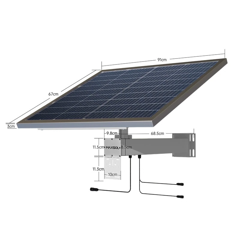
Nominal battery energy is also not the same as energy delivered to the load. For example, the documented battery specifications of the Maxsol CS8040 80W, 45Ah, 576Wh solar system are 12.8V, 45Ah and 576Wh. It also documents an 80W monocrystalline panel, MPPT controller and three DC12V outputs, with RS485 optional. The 576Wh figure is nominal battery energy; it is not a guarantee that 576Wh will reach connected devices.
Delivered energy may be lower because of:
- battery management and low-voltage protection limits;
- conversion efficiency;
- cable and connector losses;
- temperature-dependent protection;
- controller and auxiliary consumption;
- battery condition and configuration;
- the minimum reserve selected by the designer.
Do not compare amp-hours without voltage
Amp-hours alone are not a valid basis for comparing batteries at different voltages. Convert each battery to nominal watt-hours:
Nominal Wh = nominal voltage × amp-hours
A 45Ah battery at 12.8V is not energy-equivalent to a 45Ah battery at another voltage. The same rule applies when replacing an existing battery or comparing integrated solar systems.
For the full calculation process, use a CCTV off-grid solar sizing method based on load energy and autonomy. Battery chemistry, protection and usable-energy considerations are covered separately in this guide to LiFePO4 battery benefits and limitations for solar CCTV.
Fault-isolation check for dawn shutdown
If the system stops shortly before sunrise:
- Record battery voltage at sunset, midnight and immediately before shutdown.
- Measure voltage at both the battery terminals and the load terminals.
- Identify whether the battery, controller or converter initiates the cutoff.
- Log the actual night load rather than relying only on nameplate power.
- Recalculate overnight energy, including every device and conversion stage.
- Compare the result with a conservative estimate of usable delivered energy.
A large difference between battery-terminal voltage and equipment-terminal voltage indicates a distribution problem, not necessarily insufficient battery capacity.
Sizing for average sunshine instead of the design month
Annual-average solar resource is useful for broad comparison but can hide the period when an off-grid site is most likely to fail. In the Philippines, the relevant design period depends on the site’s local weather, terrain, shading and operating requirement. It should not be replaced with an invented national “sun-hours” figure.
Imported troubleshooting guides may describe this symptom as a “winter-only outage.” For a Philippine installation, the equivalent may be failure during the lowest-resource month, an extended cloudy sequence or a season when nearby vegetation and terrain create more shade.
The correct question is not, “Can the array replace one average day of energy?” It is:
Can the array replace the load energy, system losses and required recovery energy during the selected critical design period?
Recharge capacity is different from load capacity
A system may have enough battery capacity to run through one night but too little PV capacity to restore that energy the next day. The battery then starts each evening at a lower state of charge until the low-voltage cutoff is reached.
For a hypothetical design assumption, suppose a site consumes 600Wh daily and loses a further design allowance through conversion, wiring and control electronics. An array that delivers only enough usable energy to match part of that total cannot recharge the battery fully, even if its panel wattage appears large compared with the instantaneous load.
When troubleshooting failure to recharge, check:
- PV voltage at the controller input;
- charging current over the available daylight period;
- whether the controller reaches its expected charging stages;
- shade at different times of day, not only during inspection;
- dirt, leaves, structures and growing vegetation;
- array orientation and mounting angle;
- battery charging temperature limits and active protection;
- controller PV voltage, current and power limits;
- energy consumed while the battery is recharging.
The Maxsol CS12060 120W, 60Ah, 768Wh solar system is one selection reference with a documented 120W monocrystalline panel, 12.8V 60Ah 768Wh LiFePO4 battery, MPPT controller and three DC12V outputs; RS485 is optional. These nominal figures do not establish universal autonomy or recharge time. Confirm the current datasheet, supplied configuration, controller limits and site-specific energy balance.
Omitting night loads, conversion loss and startup demand
A daytime spot measurement rarely represents a solar-powered CCTV or wireless site’s worst operating condition. Cameras may activate infrared illumination at night, radios may draw different power during transmission, and converters may consume more input power than the connected load receives.
Build the load schedule by operating mode:
| Load category | What designers commonly miss | Measurement approach |
|---|---|---|
| Camera | IR illumination, heater or other enabled functions | Measure day and night input separately |
| Wireless radio or CPE | Traffic-dependent consumption and startup behaviour | Log input power during boot and representative operation |
| Network equipment | All connected devices and auxiliary electronics | Measure total DC input rather than adding only headline ratings |
| DC converter | Conversion loss and no-load consumption | Measure input and output power at the intended voltage |
| Enclosure equipment | Fans, controllers, relays, sensors or lighting | Include every load connected to the battery |
| Cabling | Voltage drop that increases current or causes cutoff | Measure voltage at source and load under peak demand |
Repeated PoE reboots are not always battery failures
A PoE device that starts, reboots and starts again may be causing a cyclic fault:
- The device begins booting.
- Its power demand rises.
- Cable or converter voltage drops.
- The device resets.
- Demand falls and voltage recovers.
- The cycle repeats.
Measure converter input voltage, converter output voltage and device-end voltage during startup. A normal battery reading taken after the reboot can conceal the short voltage collapse that caused it.
Also verify whether the stated PoE power is input power or output power. If a powered device needs a given output, the source must provide that output plus converter and wiring losses.
For a hypothetical calculation only, if a converter delivered 90% efficiency at the actual operating point, a 27W output would require approximately 30W of input before cable losses:
27W ÷ 0.90 = 30W
The 90% figure is an assumed calculation value, not a claim for a linked product. Actual efficiency varies with voltage, load, temperature and converter design.
Startup demand must also fit within the continuous and transient limits of the battery protection, controller output, converter, fuse, connectors and cable. Do not solve a reboot by installing a larger fuse unless the conductors and all upstream components are rated for it.
Mismatching battery, MPPT and PoE interfaces
Correct energy sizing cannot compensate for incompatible electrical interfaces. The battery, PV array, MPPT controller, DC outputs, converter and powered device must agree on voltage range, current, polarity, connector arrangement and protocol.
MPPT input must match the PV array
Confirm the controller’s documented:
- maximum PV open-circuit voltage;
- permitted PV operating-voltage range;
- maximum input current;
- maximum PV power;
- supported battery voltage and chemistry;
- charging profile and temperature restrictions;
- protection and restart behaviour.
Check the array’s open-circuit voltage against the controller limit at the lowest anticipated module temperature. Also check current and power limits under plausible operating conditions. Do not assume that an MPPT controller can accept any panel simply because the nominal battery voltage matches.
A controller may stop charging, limit output or sustain damage if the input falls outside its permitted range. Where specifications conflict between a label, manual and sales page, confirm the current datasheet and supplied configuration rather than choosing the most convenient value.
Adjustable PoE voltage does not establish PoE compatibility
The documented Maxsol POE24V DC-to-PoE converter accepts 12–36V DC input and provides adjustable 12–57V PoE output, Gigabit Ethernet and an LCD voltage display. Its documented continuous load for 12V-to-48V conversion is at most 30W. The stated efficiency of up to 94% is a maximum, not a value that should be assumed for every design point.
Those facts alone do not establish IEEE powered-device detection or negotiation. Before connecting a camera, access point, radio or bridge, verify:
- required input voltage and acceptable tolerance;
- maximum continuous and startup power;
- passive or negotiated PoE requirement;
- polarity and powered-pair pinout;
- Ethernet speed requirement;
- cable resistance and total run length;
- converter input voltage under maximum load;
- environmental and enclosure temperature limits.
The linked solar systems and converter are selection examples, not a tested compatible bundle. Compatibility must be checked for the exact powered device, cabling and supplied product configuration.
Ignoring shading, temperature and maintenance access
A design can pass an electrical calculation and still fail because its physical installation was not evaluated.
Shade must be checked over time
A site inspection at midday may miss morning or afternoon shade from poles, buildings, trees, antennas or terrain. Even small obstructions can reduce available charging energy, particularly when they affect the array during the limited useful solar window of a low-resource day.
Inspect or model shading across the expected operating year. Allow for vegetation growth and new equipment mounted near the panel. If the site depends on a narrow clear-sky window, the design has little tolerance for weather or soiling.
Enclosure temperature can change system behaviour
An outdoor enclosure exposed to direct sun may be substantially hotter inside than the surrounding air. High internal temperature can affect controller output, converter loading, connector resistance and battery protection. Battery charging may also be restricted outside the permitted temperature range.
Measure temperature where the electronics and battery are actually installed. The ambient reading outside the box is not enough. Review:
- enclosure solar exposure and external shading;
- spacing around heat-producing components;
- ventilation method and water-ingress implications;
- cable gland placement;
- conductor and terminal temperature;
- equipment derating requirements;
- battery charging and discharging temperature limits.
Never add unplanned openings that defeat the enclosure’s required environmental protection. Thermal control must be considered together with rain, dust, insects, condensation and tampering risks.
Maintenance access is part of reliability
Installers should be able to reach fuses, isolators, terminals, indicators and communication interfaces without dismantling the whole site. Provide clear labels, a wiring diagram, safe test points and enough cable service loop for inspection.
If RS485 monitoring is needed on a linked Maxsol solar system, confirm that the optional feature is included in the supplied configuration. Do not assume optional monitoring is present.
Inaccessible components increase repair time and encourage unsafe testing. They also make it harder to distinguish a weak battery from a loose terminal, damaged cable, shaded panel or incompatible converter.
Validate the corrected design with a commissioning checklist
Commissioning should verify the energy model and interfaces under realistic operating conditions. A single no-load voltage reading is not sufficient.
Load and energy
- List every camera, radio, access point, converter, controller and enclosure auxiliary.
- Record separate daytime, nighttime and startup power.
- Convert all operating schedules to Wh per day.
- Include conversion, cable and control-system losses.
- Keep nominal battery Wh separate from estimated usable delivered energy.
- Select and document the required autonomy and design reserve.
PV and charging
- Use the selected critical design period rather than annual-average sunshine alone.
- Check shading at relevant times and seasons.
- Confirm array voltage, current and power against MPPT limits.
- Record PV input and battery charging current during commissioning.
- Verify that the battery recovers after the planned overnight discharge.
- Confirm battery charging temperatures and protection behaviour from current documentation.
Battery and DC distribution
- Measure battery-terminal voltage and load-terminal voltage under peak load.
- Calculate cable voltage drop for the actual current and distance.
- Confirm conductor, connector, fuse and isolator ratings.
- Verify low-voltage cutoff and restart behaviour.
- Label polarity and all distribution outputs.
- Keep test points and protection devices accessible.
PoE and networking
- Verify voltage, polarity, pinout and protocol for every powered device.
- Confirm converter continuous capacity and startup headroom.
- Measure voltage at the far end of the Ethernet cable during boot.
- Check the required Ethernet data rate.
- Test all intended night functions, including IR operation.
- Confirm that a reboot does not trigger a repeating undervoltage cycle.
Environment and handover
- Measure enclosure temperature during a representative high-temperature period.
- Check component spacing, ventilation and cable-gland sealing.
- Confirm panel and enclosure access for cleaning and service.
- Record installed settings, firmware where applicable, wiring and protection values.
- Save baseline voltage, current, temperature and load readings for later fault comparison.
- Document optional monitoring features actually included in the supplied configuration.
After correcting the design, compare the linked Maxsol selection examples against the project’s actual port count, load, cable distance, power budget, environment and management requirements. Use current datasheets and the supplied configuration to confirm each electrical and physical interface before procurement or installation.