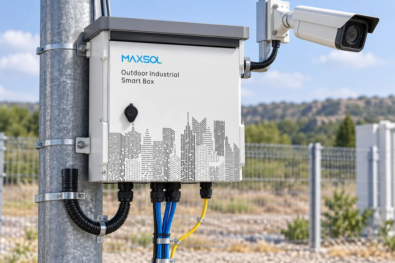
Solar PoE vs Grid Power for Remote Philippine Sites
Compare solar PoE and grid-fed outdoor PoE for remote Philippine sites by distance, civil works, uptime, maintenance, monitoring and lifecycle cost.
By Maxsol Team

Solar PoE is usually the stronger option when a remote camera, wireless bridge or sensor site has no practical grid connection and extending AC power would require substantial trenching, cabling or utility work. Traditional grid-fed outdoor PoE is often better where dependable AC power already exists near the equipment and the installation needs predictable operation without relying primarily on solar generation.
There is no universal winner in the solar PoE vs traditional power remote sites comparison. The correct architecture depends on the same defined network load, required operating hours, site distance, solar exposure, acceptable recovery time and maintenance capability. In some Philippine deployments, the most resilient answer may be grid power with battery backup, solar with sufficient autonomy, or a hybrid system rather than either source alone.
Define the same remote-site load and service objective
A fair comparison must begin with one service objective. Comparing a small solar camera node against a grid-powered cabinet carrying several high-power devices will produce a misleading conclusion.
Create a load schedule covering every device that must operate at the site:
- IP cameras, including night-time infrared or illuminator demand
- Wireless access points and point-to-point or point-to-multipoint radios
- PoE extenders, switches, media converters and fibre equipment
- Sensors, access-control devices or other auxiliary loads
- Cabinet fans, heaters or environmental controls, if required
- Battery management and power-conversion losses
- Temporary power peaks during start-up, radio transmission or camera movement
Record the normal load, expected peak load and number of operating hours per day. A 24/7 surveillance node has a different energy requirement from equipment that operates only during scheduled periods.
The service objective should also specify:
- Required availability: Must all devices remain online continuously, or can selected loads be disconnected during a low-energy condition?
- Acceptable outage duration: Can the site tolerate a short restart, or must it ride through extended loss of input power?
- Recovery method: Should the system recover automatically, or is a site visit acceptable?
- Critical and non-critical loads: Which ports or devices should receive power first?
- Communications path: Does the site use fibre, wireless backhaul or copper Ethernet?
- Growth allowance: Will more cameras, radios or sensors be added later?
For solar, calculate daily energy in watt-hours rather than looking only at the PoE switch’s watt rating. For grid-fed PoE, check both the continuous PoE budget and the backup energy required during an AC interruption. In either case, allow reasonable design margin without assuming that an oversized power supply automatically creates longer autonomy.
For a detailed introduction to the components and sizing sequence, see this guide to solar-powered PoE for off-grid networking.
Compare energy-source conversion and distribution
The main architectural difference is not Ethernet. It is how energy reaches the PoE switch and how many conversion, storage and protection stages sit between the source and the powered devices.
Solar PoE architecture
A typical solar PoE site may include:
- PV modules
- Charge-control equipment
- Battery storage
- DC protection and isolation
- A solar-compatible PoE switch or DC power system
- Surge and grounding provisions
- Ethernet, fibre or wireless backhaul
Solar energy varies through the day, while the network load may run continuously. The battery therefore carries the system when PV production is below demand. Array size, battery capacity, charging limits, seasonal conditions, shading and conversion losses all affect autonomy.
A DC-oriented design can reduce unnecessary conversion stages where the battery, network switch and loads have compatible voltage requirements. That does not make every direct-DC design automatically efficient or compatible. The installer must still confirm battery voltage range, charging behaviour, cable voltage drop, PoE mode and the input requirements of connected devices.
The Maxsol IOT2802SFG-S managed solar industrial PoE switch illustrates this architecture. Its documented context includes eight Gigabit PoE ports, two SFP ports, a 120W PoE budget, 90W BT support, PV and battery monitoring, and PV and battery input at DC22–29.2V. Ports 3–4 can be configured for 24V or 48V PoE. Actual port allocation, charging limits, connected-device requirements and battery compatibility must be verified before specification.
Grid-fed outdoor PoE architecture
A traditional remote-site arrangement normally starts with AC power from a utility connection or another established AC source. The cabinet then converts AC to the DC voltage required by the PoE switch. A UPS or integrated battery stage can maintain operation if the AC source fails.
Typical components include:
- AC feeder and disconnect
- Circuit and surge protection
- AC-to-DC power supply
- Outdoor PoE switch
- UPS or backup battery, when required
- Cabinet or weather-resistant enclosure
- Fibre, wireless or copper uplink
The Maxsol SBOX2802SFG-I managed industrial smart Ethernet box is an example of a grid-fed outdoor architecture. It is documented as IP65 and combines eight Gigabit PoE ports, two Gigabit SFP slots, Layer 2 management, AC100–240V input and a built-in 240W DC55V UPS module.
These two Maxsol products illustrate different architectures; they are not a tested equivalent pair. Their input arrangements and power functions differ, so they should be compared against the project requirement rather than treated as interchangeable models. Backup time, solar autonomy and total system cost depend on the verified site design.
| Comparison point | Solar PoE | Grid-fed outdoor PoE |
|---|---|---|
| Primary energy source | PV generation with battery storage | Established AC supply |
| Main sizing basis | Daily energy, peak load and required autonomy | Peak load, continuous PoE budget and backup duration |
| Storage role | Usually central to night-time and low-sun operation | Optional or used for outage backup |
| Conversion path | Often PV to battery/DC to PoE | Usually AC to DC to PoE |
| Main energy risk | Insufficient generation, shading or battery depletion | AC interruption or feeder failure |
| Monitoring priority | PV, battery, charging state and load | AC status, UPS condition, PoE ports and network health |
| Expansion constraint | Array, battery, controller and PoE capacity | Feeder, power supply, UPS and PoE capacity |
Evaluate installation distance and civil work
Distance from the nearest usable power source can influence the choice more than the switch price.
If AC power is already available at a nearby building, pole or secure equipment room, grid-fed outdoor PoE may have the simpler installation scope. If the site is across a roadway, agricultural area, coastline, open compound or difficult terrain, extending power may involve long cable runs, excavation, reinstatement, additional enclosures and coordination with other parties.
Solar can avoid a long AC feeder, but it does not eliminate site work. The project may still require:
- A structurally suitable PV mounting location
- Unshaded solar access during relevant hours
- A secure battery and electronics enclosure
- Foundations, poles or mounting frames
- Correct cable sizing and short DC power runs where practical
- Earthing, bonding and surge protection
- Safe access for inspection and battery replacement
- Fibre or wireless backhaul to the main network
Do not assume PoE can cover any distance merely because power generation is located at the endpoint. Standard Ethernet channel limits and the selected network design still apply. Fibre is commonly considered for long-distance uplinks because it separates the data path from copper-distance limitations, but its transceivers, termination method and switch compatibility must be checked.
A wireless bridge can reduce trenching, although it introduces line-of-sight, alignment, interference and mounting considerations. For Philippine sites exposed to heavy rain, strong winds, salt-laden air or intense heat, the physical design should account for actual site exposure rather than relying only on a broad “outdoor” label.
Before choosing an enclosure and distribution arrangement, review the practical differences among power input, fibre, battery and outdoor switching in this outdoor PoE switch box and power design guide.
Compare the full construction boundary
Ask each bidder or design team to include the same scope:
- Source connection or PV modules
- Battery storage and containment
- Poles, brackets and foundations
- Trenching, conduits and reinstatement
- Power and data cables
- Protection, grounding and isolation
- Enclosures and environmental controls
- Configuration and commissioning
- Remote monitoring setup
- Initial spares and planned replacements
Leaving civil work out of one option can make it look artificially inexpensive. Conversely, assuming major trenching where an existing compliant feeder is available can unfairly favour solar.
Compare monitoring, maintenance and recovery
Remote sites should be designed around faults that can be detected and resolved without unnecessary travel. A low-cost architecture can become difficult to operate if every battery warning, locked camera or power interruption requires a technician to visit.
What to monitor in a solar PoE system
Useful solar-site information includes:
- PV input status
- Battery voltage or state information supported by the system
- Charging condition
- Load or PoE port status
- Low-energy alarms
- Device reachability
- Temperature or enclosure alarms, where fitted
- Historical trends that help distinguish a temporary event from a declining component
Solar maintenance may include cleaning PV modules when site conditions require it, checking for new shading, inspecting mounting hardware and cables, reviewing battery condition, and confirming that drainage and seals remain effective.
Recovery planning should define what happens when available energy falls below the required level. Possible strategies include disconnecting non-critical loads, scheduling selected equipment, restarting a PoE port remotely, or preserving power for the communications link and highest-priority camera. These functions must be supported by the selected equipment and deliberately configured; they should not be assumed.
What to monitor in a grid-fed system
For a grid-powered cabinet, monitor:
- Presence or loss of AC input
- UPS or battery status
- PoE port consumption and link condition
- Switch temperature and alarms
- Fibre or wireless uplink status
- Repeated device restarts
- Surge-protection condition where indication is available
Grid-fed sites still need battery maintenance if backup is installed. A UPS should not be treated as indefinite backup: runtime depends on battery capacity and condition, actual load, conversion efficiency, temperature and the UPS operating limits.
Plan recovery before failure
For both architectures, establish:
- Which alarms are sent and to whom
- Whether remote PoE cycling is available
- The order in which loads restart
- The lowest acceptable battery condition
- When a site visit is triggered
- Which replacement parts technicians should carry
- How configuration backups are stored
- How the system behaves after a prolonged shutdown
Remote management improves visibility, but it cannot repair damaged cabling, a failed battery, a displaced solar panel or a flooded enclosure. Physical inspection remains necessary at intervals appropriate to the environment and criticality of the site.
Model lifecycle costs without invented prices
A meaningful lifecycle comparison should use project-specific quotations and a defined evaluation period. It should not depend on generic savings percentages, assumed electricity prices or an unsupported payback claim.
Use a cost model with these categories:
Initial project cost
For solar PoE, include:
- PV modules and mounting
- Battery storage
- Charge control and DC distribution
- Solar-compatible PoE equipment
- Enclosure, protection and grounding
- Foundations and installation labour
- Backhaul equipment
- Commissioning and monitoring setup
For grid-fed outdoor PoE, include:
- Utility or site-power connection work
- AC feeder, conduit and trenching
- AC protection and isolation
- Outdoor cabinet and PoE equipment
- UPS and batteries, if required
- Fibre or wireless backhaul
- Reinstatement and commissioning
Recurring operating cost
Consider:
- Electricity charges for grid-fed equipment
- Scheduled inspections
- Remote-monitoring platform costs, if any
- Vegetation or shading management
- PV cleaning where needed
- Enclosure and cooling maintenance
- Travel, access and technician time
- Replacement of consumable or ageing components
Replacement and failure cost
Battery replacement should be modelled for both architectures when batteries are used. Also include plausible replacement events for power supplies, surge-protection components, fans, network equipment and damaged cabling. Use supplier documentation and the project’s environmental assumptions rather than inventing service-life figures.
Downtime may also carry a business cost. Instead of assigning an arbitrary amount, document the consequence:
- Loss of surveillance recording
- Loss of live monitoring
- Interruption of wireless connectivity
- Need for temporary security measures
- Technician mobilisation
- Delayed operations at the remote site
Residual and expansion cost
Evaluate whether the original system can support expected growth. Adding one high-power camera may require more than a free Ethernet port. In a solar system, it can affect the PoE budget, daily energy balance, PV capacity and battery autonomy. In a grid-fed system, it can affect the feeder, power supply, UPS runtime and thermal load.
A simple lifecycle model can use:
Total evaluated cost = initial project cost + recurring operating cost + planned replacements + expected maintenance and recovery cost + expansion cost
Keep the same evaluation period, load forecast, backup objective and labour assumptions for both options. Run sensitivity checks for battery replacement timing, energy cost, site visits, civil-work scope and future loads rather than presenting one estimate as certain.
Select solar, grid or hybrid architecture by evidence
Choose the architecture only after the load, environment, construction boundary and recovery objective are documented.
Solar PoE is generally a stronger candidate when
- No practical AC source is available at the endpoint.
- Extending power requires disproportionate trenching or difficult civil work.
- The site has suitable solar exposure and a secure mounting area.
- The daily load and autonomy requirement can be supported by a verified energy design.
- PV and battery status can be monitored.
- Planned maintenance access is available.
- The network can use fibre or a suitable wireless backhaul.
Grid-fed outdoor PoE is generally a stronger candidate when
- A dependable AC source is already close to the equipment.
- The site has a high or expanding continuous load.
- Solar access is restricted by persistent shading or mounting limitations.
- Long periods of battery-only operation are not required.
- Existing maintenance teams already support AC cabinets and UPS equipment.
- Construction and protection requirements are known and manageable.
Consider a hybrid or backup design when
A hybrid design can combine different sources or recovery paths—for example, grid power with battery backup, or a solar-led site with an approved secondary charging source. It may be appropriate where service continuity matters more than architectural simplicity.
However, hybrid systems introduce additional controls, protection devices, operating states and failure modes. Confirm:
- Which source has priority
- Whether automatic transfer is supported
- Charging compatibility
- Battery voltage and chemistry requirements
- Isolation between sources
- Alarm behaviour during transfer
- Restart sequence after full shutdown
- How technicians can safely isolate each source
Do not call a design “hybrid” merely because it contains a battery. A battery-backed grid cabinet is still primarily grid-fed unless another generation source is deliberately integrated.
Final selection checklist
Before approving either architecture, verify:
- Measured or documented normal and peak loads
- Required runtime and acceptable outage duration
- PoE voltage, power class and device compatibility
- Switch PoE budget and actual port allocation
- PV input and charging limits for solar equipment
- Battery voltage, chemistry, capacity and environmental suitability
- AC input and UPS arrangement for grid-fed equipment
- Ethernet distance and uplink design
- Fibre module or wireless bridge compatibility
- Enclosure rating and site-specific exposure
- Grounding, surge protection and safe isolation
- Monitoring, alarms and remote recovery functions
- Civil works and access requirements
- Expansion allowance
- Lifecycle cost assumptions and replacement plan
The practical next step is to compare the linked Maxsol models against your required port count, actual device load, site distance, power source, environmental conditions, uplink method and management needs. Confirm all battery, charging, port-allocation, backup and compatibility details as part of the final site design rather than selecting solely by product category.