Solar Power and PoE Off-Grid Networking Guide
Learn how solar, batteries and PoE support off-grid cameras and access points, with checks for voltage, negotiation, load and expected runtime.
By Maxsol Team

Solar power and Power over Ethernet (PoE) can work together to operate cameras, wireless access points and other network devices where grid electricity is unavailable. The solar system supplies and stores energy, while a compatible PoE interface places that energy onto the Ethernet cable. Network data still has to come from a separate source, such as a switch, router, recorder or wireless bridge.
Successful solar power and PoE off-grid networking depends on more than matching wattage. The battery voltage, converter input range, PoE output voltage, polarity, pinout and negotiation method must all suit the powered device. An adjustable voltage control alone does not make a converter compliant with IEEE PoE.
Trace the solar energy and Ethernet data paths
An off-grid PoE installation has two related but distinct paths: an energy path and a data path.
Solar energy path
A typical DC-powered architecture follows this sequence:
- Photovoltaic panel: Converts sunlight into DC electricity.
- Solar charge controller: Regulates power from the panel to charge the battery safely.
- Battery: Stores energy for night-time use and periods with limited sunlight.
- DC-to-PoE interface: Converts or regulates battery-side DC and injects it into the required Ethernet conductors.
- Powered device: Receives both power and network data through its Ethernet port.
The charge controller is not normally the PoE injector. Likewise, the battery should not be connected straight to a PoE port unless the complete voltage, polarity and pin arrangement have been designed for that specific device.
A direct DC architecture can avoid the extra conversion stage of changing battery DC into AC and then back into DC through a conventional mains-powered PoE adaptor. However, direct DC operation is only appropriate when every voltage and interface is compatible.
Ethernet data path
The data path may be:
- Network switch to PoE interface to camera
- Network video recorder to PoE interface to camera
- Router to PoE interface to wireless access point
- Wireless bridge or customer-premises equipment to PoE interface to a remote device
The solar panel, controller and battery do not create an Ethernet connection. If a remote camera needs to send video to another site, the design still requires a data backhaul. Depending on the project, this could be fibre, copper Ethernet, point-to-point wireless, mobile connectivity or local recording.
A useful way to troubleshoot an off-grid site is to test the paths separately. First confirm stable battery-side power and PoE output. Then confirm Ethernet link, addressing and communication. A device may have power but no data, or a valid network path but insufficient power.
Separate charging, storage and PoE functions
Each part of the system has a different responsibility. Treating one component as if it can perform all functions is a common cause of unreliable installations.
| Function | Typical component | What must be checked |
|---|---|---|
| Harvest solar energy | PV panel | Rated power and controller-compatible voltage and current |
| Regulate charging | Solar charge controller | PV limits, battery profile, protection and temperature conditions |
| Store energy | Battery | Nominal voltage, usable energy, current capability and permitted operating conditions |
| Convert DC voltage | DC converter | Input range, regulated output and continuous load limit |
| Inject Ethernet power | PoE injector or PoE switch | Protocol, voltage, polarity, pinout and total power capacity |
| Carry network traffic | Switch, router, recorder or wireless bridge | Port speed, addressing, bandwidth and backhaul availability |
| Use power and data | Camera, access point or other powered device | Accepted PoE type, voltage range and maximum demand |
For example, the Maxsol CS12060 solar power system documents a 120W monocrystalline panel, a 12.8V 60Ah 768Wh LiFePO4 battery, an MPPT controller and three DC12V outputs. RS485 is optional. These details help define the power platform, but they do not by themselves establish how long a particular camera will operate or whether a specific PoE device is compatible.
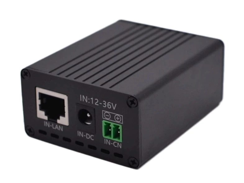
A separate Maxsol POE24V DC-to-PoE converter accepts 12–36V DC and provides adjustable 12–57V PoE output, Gigabit Ethernet and an LCD voltage display. Its documented continuous load when converting from 12V to 48V is at most 30W. IEEE powered-device detection or negotiation is not established by those facts, so protocol, voltage, polarity and pinout must be verified before connecting equipment.
The linked solar system and converter are selection examples, not a tested compatible bundle. Confirm the current datasheets and supplied configurations for both products, including controller PV limits, battery charging temperatures, protection behaviour and connector arrangements.
Distinguish passive PoE from IEEE negotiation
Passive PoE and standards-based IEEE PoE can use similar Ethernet cabling, but their connection behaviour is different.
Passive PoE
A passive injector generally applies voltage to selected Ethernet conductors whenever it is powered. It may not check whether the device is PoE-capable before energising the cable.
Compatibility therefore depends on manually matching:
- Output voltage
- Positive and negative polarity
- Powered conductor pairs or pinout
- Device power demand
- Cable and connector arrangement
Connecting passive power with the wrong voltage, polarity or pinout can damage equipment. A label such as “adjustable PoE” does not remove this risk.
Negotiated IEEE PoE
IEEE 802.3af, 802.3at and 802.3bt systems use detection and negotiation procedures between power-sourcing equipment and the powered device. A compliant source checks for a valid powered-device signature before applying full power and may classify the device’s demand.
| Attribute | Passive PoE | Negotiated IEEE PoE |
|---|---|---|
| Power application | May be continuously present | Applied after powered-device detection |
| Voltage selection | Often fixed or manually adjustable | Defined by the applicable IEEE system |
| Device detection | Not necessarily provided | Required as part of standards-based operation |
| Compatibility method | Manual voltage, polarity and pin matching | Standards compliance plus required power class |
| Main risk | Incorrect power may reach an incompatible port | Insufficient class, port budget or implementation mismatch |
A converter with a 48V setting is not automatically an IEEE 802.3af or 802.3at injector. Output voltage is only one requirement. Detection, classification, power delivery behaviour and conductor use also matter.
For an existing PoE camera, check its label and current datasheet for wording such as:
- IEEE 802.3af powered device
- IEEE 802.3at or PoE+ powered device
- Passive 24V PoE
- Passive 48V PoE
- 12V DC input plus separate Ethernet
- Maximum power consumption and startup demand
If the camera requires negotiated IEEE PoE, select a DC-powered injector or switch that explicitly documents the required IEEE standard. Do not assume that a passive converter will start the camera safely just because its voltage can be adjusted to the same nominal level.
Match battery and converter operating voltages
Voltage compatibility must be checked across the full operating range, not only at the nominal values printed on product names.
A battery described as 12V or 12.8V does not remain at exactly that voltage throughout charging and discharge. Its terminal voltage changes with state of charge, load, temperature and controller behaviour. The converter’s permitted input range must cover the battery-side voltage under all intended conditions.
Review the following interfaces:
Panel to charge controller
Confirm the panel’s open-circuit voltage, operating voltage, short-circuit current and power against the controller’s PV input limits. Do not connect panels based only on their watt rating.
Controller to battery
The controller must support the battery chemistry, nominal voltage and required charging profile. Battery charging temperature limits and low-temperature protection are especially important where equipment may be installed in elevated, exposed or unusually cool locations.
Battery or DC output to converter
Check:
- Minimum and maximum input voltage
- Maximum input current
- Connector type and polarity
- Cable size and allowable voltage drop
- Fuse or branch-circuit protection
- Low-voltage shutdown behaviour
The POE24V example accepts 12–36V DC, but installers must still confirm that the actual power system remains within this range and can supply the required current.
Converter to powered device
Confirm:
- Required PoE voltage
- Acceptable voltage tolerance
- Passive or negotiated operation
- Positive and negative pin assignment
- Maximum continuous power
- Startup or inrush demand
- Ethernet speed requirements
Long cable runs introduce voltage drop. Use outdoor-rated, solid-copper Ethernet cable appropriate for the installation, and avoid treating copper-clad aluminium cable as electrically equivalent. For passive PoE in particular, measure the expected voltage at the device end under load rather than relying only on the unloaded converter display.
Budget continuous and startup demand
An off-grid PoE power budget should include every load that remains connected, not just the camera’s headline wattage.
Possible loads include:
- Camera electronics
- Infrared illuminators
- Motorised pan, tilt or zoom functions
- Lens heaters, blowers or defogging systems
- Wireless bridges and access points
- Ethernet switches
- Routers or mobile gateways
- Recorders and storage devices
- DC converters and controller self-consumption
Startup demand can be higher than normal operating consumption. A camera may draw more power when its infrared lighting switches on, a heater starts, or a motor moves. Wireless equipment can also have short peaks during boot-up or transmission.
For port-level planning, see the separate guide to calculating a PoE power budget for security cameras. That process should be completed before solar and battery sizing so the energy system is based on the realistic total load.
Hypothetical demand example
The following is a hypothetical design assumption, not measured product performance.
Suppose a remote camera averages 12W, while a wireless bridge and the required conversion stages add another assumed 6W. The assumed continuous system demand is therefore 18W. Over 24 hours, the connected load alone would require:
18W × 24 hours = 432Wh per day
That figure is not yet the required battery or solar-panel size. The design would still need to account for:
- Conversion losses
- Battery reserve
- Allowed depth of discharge
- Reduced solar collection during poor weather
- Controller and cable losses
- Battery temperature
- Component ageing
- Seasonal operating conditions
- Startup peaks
The documented 768Wh battery figure for the CS12060 is nominal stored energy, not guaranteed usable energy at the PoE device. There is no universal runtime that can be calculated from nominal watt-hours alone.
Likewise, the POE24V’s documented conversion efficiency of up to 94% is a maximum value, not a guaranteed design efficiency under every voltage and load condition. Use verified operating data and an appropriate engineering margin rather than designing around the maximum figure.
For the broader energy calculation, including autonomy and solar recharge, follow a dedicated process for sizing an off-grid solar power system for CCTV. Avoid selecting the panel merely because its watt rating exceeds the camera’s wattage; the system must also restore the energy used overnight and maintain reserve for limited-sun periods.
Review a compatible architecture checklist
Before purchasing or connecting equipment, document the complete architecture from the PV panel to the network endpoint.
Solar and charging
- PV voltage, current and power are within the controller’s limits.
- The controller supports the selected battery chemistry and nominal voltage.
- Battery charging and discharge temperatures suit the site conditions.
- Required overcurrent, reverse-polarity and surge protection has been specified.
- Panel placement accounts for practical shading and mounting constraints.
- The design includes reserve for periods of reduced solar generation.
Battery and DC distribution
- Battery voltage remains within the converter input range throughout operation.
- Battery and controller outputs can supply both continuous and startup current.
- DC cable size is suitable for current, length and acceptable voltage drop.
- Each load branch has appropriate protection and isolation.
- Low-voltage shutdown behaviour will not cause repeated device rebooting.
PoE compatibility
- The powered device is identified as passive PoE or a specific IEEE PoE standard.
- Required voltage and tolerance are confirmed from the current device datasheet.
- Polarity and powered pin pairs match.
- The injector or switch can provide the device’s maximum demand.
- Startup, infrared, heater and motor loads are included.
- The required Ethernet speed is supported end to end.
- The cable type and distance are suitable for both data and power.
Network and application
- A separate data source or backhaul is included.
- The camera or access point has a valid IP addressing plan.
- Bandwidth is adequate for video or wireless traffic.
- Local recording behaviour during backhaul failure is understood.
- Remote monitoring does not depend on equipment that lacks its own power allowance.
- Reboot and recovery behaviour has been tested before remote installation.
Outdoor environment
- Enclosures, cable glands and connectors suit rain, dust and site exposure.
- Heat produced by batteries, converters and network devices can dissipate.
- Corrosion risk is addressed at coastal or industrial sites.
- Lightning and surge exposure has been considered.
- Components remain accessible for inspection and safe isolation.
Common mistakes to avoid
Connecting the panel directly to the camera. A PV panel’s output changes with sunlight and load. A controller and battery or another properly engineered regulation stage are normally needed for stable operation.
Assuming all PoE cameras use 48V IEEE PoE. Some cameras use passive 24V, proprietary arrangements or separate DC inputs. Always check the exact model.
Treating adjustable voltage as protocol compatibility. A converter may produce the correct voltage without performing IEEE detection and negotiation.
Using nominal battery energy as delivered energy. Conversion losses, reserve limits, temperature and discharge conditions reduce the energy available at the powered device.
Forgetting the network backhaul. Solar equipment supplies electricity, not connectivity. A camera still needs a route to its recorder, monitoring station or cloud service.
Checking average load but not peak demand. Night-time infrared lighting, heaters and motor movement can trigger shutdowns even when the daytime average appears acceptable.
Building an untested remote installation. Assemble the full power and data chain before deployment. Test startup, night mode, battery recovery, link loss and restart behaviour using the intended cable lengths and device settings.
Frequently asked questions
Can a solar panel power an existing PoE camera without grid electricity?
Yes, but normally through a charge controller, battery and compatible DC-to-PoE interface. The camera’s PoE voltage, protocol, polarity, pinout and maximum demand must match the power source.
Does the PoE converter provide the camera’s internet connection?
No. It passes or combines Ethernet data from another network device. A router, switch, recorder, wireless bridge or other backhaul source is still required.
Can a passive PoE converter power an IEEE PoE camera?
Not necessarily. Matching the voltage does not establish IEEE detection or negotiation. Use a source that explicitly supports the camera’s required standard, or obtain written technical confirmation for the exact combination.
Does a 768Wh battery guarantee a specific camera runtime?
No. It is a nominal energy rating. Actual runtime depends on usable battery energy, total load, conversion losses, temperature, reserve settings, battery condition and solar recharge.
A practical next step is to document the camera or access point’s exact power interface, then compare the linked Maxsol examples against the project’s port count, continuous and peak load, cable distance, input and output power, outdoor environment, and network management requirements.