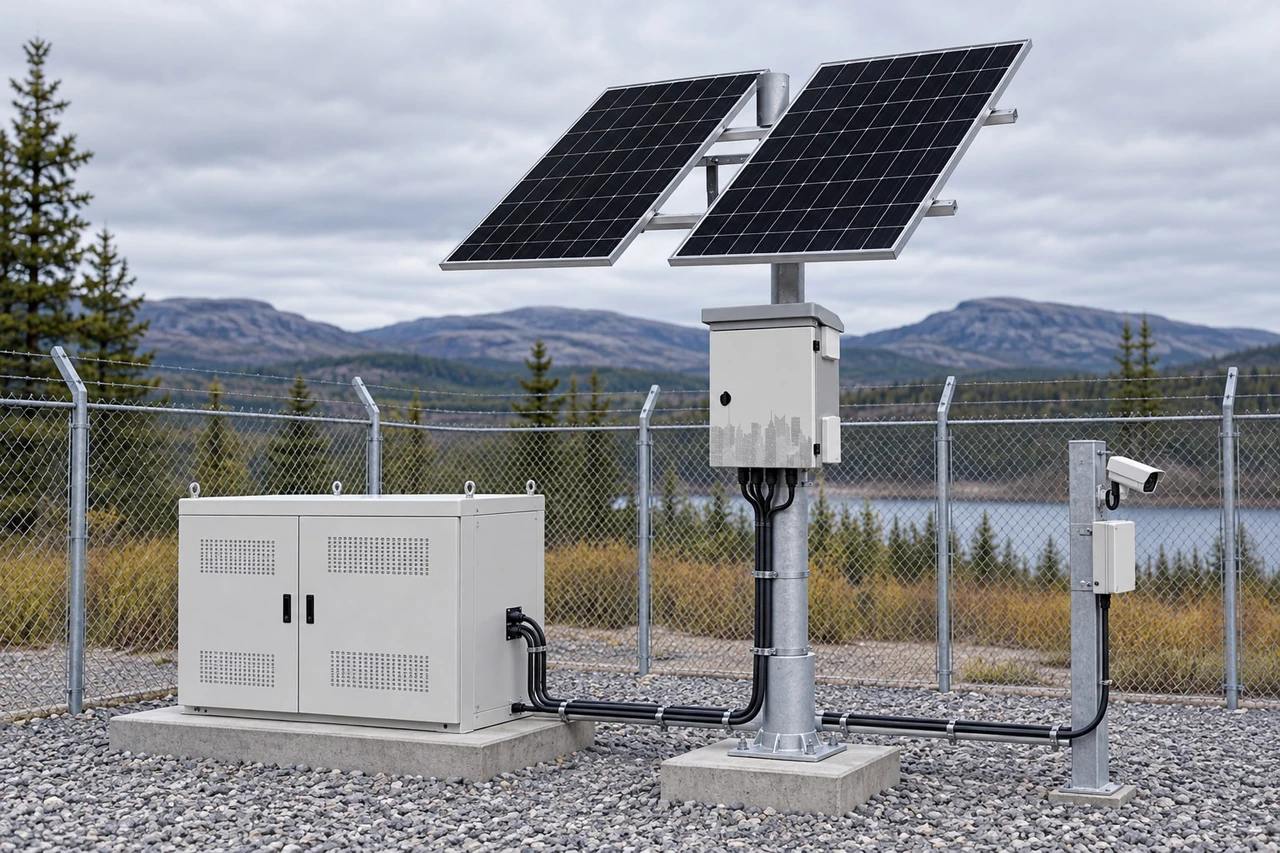
Solar Panel, Battery, MPPT and Load Calculation Guide
Use a coordinated worksheet to calculate load, battery storage, solar array and MPPT limits for off-grid sites in the Philippines.
By Maxsol Team

A reliable off-grid solar design must be calculated in this order: load, daily energy, battery storage, PV array, then MPPT controller. Each result becomes an input for the next step. Choosing a panel or battery first can leave the system unable to support the actual load, recover after poor weather, or remain within the controller’s electrical limits.
A practical solar panel battery MPPT load calculation therefore needs one coordinated worksheet. Record every assumption, use design-month solar data for the specific Philippine site, and verify all voltage, current, temperature and charging limits against current equipment datasheets.
Create the load and daily energy worksheet
Begin with the equipment that must operate, not with the advertised wattage of a solar kit. List cameras, radios, switches, routers, lighting, heaters, cooling fans and conversion equipment separately.
For each load, calculate:
Daily energy in Wh = Quantity × Operating watts × Hours per day
Use measured power where possible. A nameplate maximum may overstate normal consumption, while an estimated “typical” figure may miss start-up power, infrared illumination, radio transmit peaks or processor-heavy operation.
| Load | Quantity | Power each | Operating time | Daily energy |
|---|---|---|---|---|
| IP camera | 2 | 8W | 24 hours | 384Wh |
| Wireless radio | 1 | 10W | 24 hours | 240Wh |
| Network switch | 1 | 12W | 24 hours | 288Wh |
| Total connected load | 912Wh/day |
This is a hypothetical example, not a product rating. Actual camera power can rise when infrared LEDs, heaters, pan-tilt motors or other features activate.
Add conversion and distribution losses
The connected load is not necessarily the energy that must leave the battery. Account for losses in:
- DC-DC converters
- PoE switches or injectors
- Inverters, where AC equipment is used
- Wiring and connectors
- Output protection devices
- Equipment operating in standby
- The controller’s own consumption
A simple preliminary calculation is:
Adjusted daily energy = Connected-load energy ÷ Distribution efficiency
If the 912Wh/day load is supplied through a path estimated at 87% efficiency:
912Wh ÷ 0.87 = 1,048Wh/day
Alternatively, a designer may apply a transparent loss allowance:
912Wh × 1.15 = 1,049Wh/day
Do not apply both methods unless they represent different, clearly identified losses.
Check peak power as well as daily energy
Daily Wh determines energy capacity, but instantaneous watts and amperes determine whether the wiring, battery, controller and output circuits can carry the load.
Record at least three figures:
- Continuous load: normal combined operating power.
- Peak load: simultaneous maximum demand.
- Start-up or surge load: brief current required by motors, radios, illuminators or converters.
For a 12V output circuit:
Load current = Load power ÷ Actual output voltage
A 60W load at 12V draws approximately 5A, before allowing for conversion losses. Do not assume that an output labelled DC12V can supply any 12V device. Confirm its regulated voltage range, per-port current, total output current, connector type and polarity.
For a CCTV-specific walkthrough, see this guide to sizing an off-grid solar power system for CCTV.
Size battery storage from autonomy assumptions
Battery capacity depends on the adjusted daily energy, required autonomy, permitted depth of discharge, temperature, ageing allowance and power-conversion losses.
A useful worksheet formula is:
Required nominal battery energy = Daily energy × Autonomy days ÷ Combined usable factor
The combined usable factor may include:
- Permitted usable depth of discharge
- Battery efficiency
- Temperature derating
- Design allowance for ageing
- Conversion efficiency not already included in the load calculation
Keep each factor visible rather than hiding everything inside one unexplained margin.
Hypothetical battery calculation
Using the example daily requirement of 1,049Wh:
- Required autonomy: 2 days
- Planned usable fraction: 80%, or 0.80
- Temperature factor: 90%, or 0.90
- Ageing design factor: 85%, or 0.85
Required battery energy = 1,049 × 2 ÷ (0.80 × 0.90 × 0.85)
Required battery energy = approximately 3,428Wh nominal
For a nominal 12.8V battery:
Required Ah = 3,428Wh ÷ 12.8V = approximately 268Ah
This does not mean every project should use the example factors. Obtain the permitted depth of discharge, charge and discharge limits, temperature restrictions and expected capacity behaviour from the battery datasheet.
Nominal Wh is not delivered Wh
Battery energy is commonly presented as:
Nominal Wh = Nominal voltage × Rated Ah
For example, 12.8V × 60Ah equals 768Wh. However, 768Wh is not a promise that a 100W load will operate for 7.68 hours. Delivered runtime is reduced or affected by:
- Battery management system cut-off limits
- Permitted depth of discharge
- Load and converter efficiency
- Cable voltage drop
- Battery temperature
- Battery condition
- High discharge current
- Equipment low-voltage thresholds
The Maxsol CS12060 120W and 60Ah solar system documents a 120W monocrystalline panel, 12.8V 60Ah 768Wh LiFePO4 battery, MPPT controller and three DC12V outputs. These are documented parts of one system example, not a recommendation to recreate the system from interchangeable components.
The larger Maxsol CS400150 400W and 150Ah solar system documents two 200W modules, a 12.8V 150Ah 1920Wh LiFePO4 battery, MPPT control and four DC12V outputs. Its suitability still depends on measured load, required autonomy, design-month sunlight and verified electrical limits.
Estimate PV energy for the design month
Size the array for the most demanding operating period, not for an annual average or the best sunny month. In the Philippines, extended cloud and rain can materially reduce solar production. The relevant design month depends on the exact site, local weather pattern, horizon and shading.
Obtain credible monthly solar resource data for the installation coordinates. Then confirm conditions on site, including:
- Roofs, trees, poles and terrain that cast shadows
- Panel orientation and tilt
- Salt, dust, leaves or bird fouling
- Heat and limited rear ventilation
- Cable distance between the array and controller
- Seasonal weather and extended cloudy periods
A preliminary formula is:
Required PV watts = Daily battery energy ÷ (Design peak-sun-hours × Solar system factor)
The solar system factor accounts for practical losses such as panel temperature, wiring, controller conversion, mismatch, dirt and imperfect orientation.
Hypothetical PV calculation
Assume:
- Adjusted daily energy: 1,049Wh
- Verified design-month resource: 3.5 peak-sun-hours per day
- Combined solar system factor: 0.72
PV size = 1,049Wh ÷ (3.5 × 0.72)
PV size = approximately 416W
This calculation replaces the average daily load but does not necessarily recover a deeply discharged battery quickly.
Include recharge capacity after poor weather
Suppose the system consumes two days of stored energy during poor solar conditions and should recover that deficit over the next two suitable solar days.
Energy deficit = 1,049Wh × 2 = 2,098Wh
Daily recovery energy = 2,098Wh ÷ 2 days = 1,049Wh/day
The array must then provide:
1,049Wh daily load + 1,049Wh recovery = 2,098Wh/day
Using the same 3.5 peak-sun-hours and 0.72 system factor:
Recovery-sized PV array = 2,098 ÷ (3.5 × 0.72)
Recovery-sized PV array = approximately 833W
This shows why panel sizing and battery autonomy cannot be treated separately. More battery capacity may increase autonomy, but without enough array power and controller capacity, the system can take too long to recharge.
The recovery target should be realistic. Designing for full recovery in one day may require a much larger array and controller, while accepting a long recovery period can leave the system vulnerable to another cloudy interval.
Check MPPT voltage, current and power limits
An MPPT controller must satisfy several limits at the same time. An acceptable wattage rating alone does not prove compatibility.
Verify the following on the current controller and module datasheets:
- Maximum PV open-circuit voltage
- MPPT operating voltage range
- Minimum voltage needed to begin charging
- Maximum PV input current
- Maximum short-circuit current, if specified separately
- Maximum charging output current
- Permitted PV power for the selected battery voltage
- Supported battery chemistry and charge profile
- Operating and charging temperature limits
For a practical comparison of controller approaches, review MPPT versus PWM for outdoor solar charging.
Check cold-weather open-circuit voltage
Panel open-circuit voltage rises as cell temperature falls. The controller must remain below its maximum PV input voltage under the coldest credible site condition, not only at the module’s standard test rating.
A preliminary calculation is:
Cold string Voc = Modules in series × Module Voc × [1 + |Voc temperature coefficient| × (25°C − Minimum cell temperature)]
Suppose a hypothetical panel has:
- Voc: 41V
- Voc temperature coefficient: −0.28% per °C
- Two modules in series
- Minimum design cell temperature: 10°C
Convert 0.28% to 0.0028:
Cold string Voc = 2 × 41 × [1 + 0.0028 × (25 − 10)]
Cold string Voc = approximately 85.4V
The controller’s maximum PV voltage must exceed the calculated value with an appropriate design margin. Use the module manufacturer’s exact coefficient and a defensible minimum temperature for the actual site. Cooler elevated locations may require a different assumption from warm lowland sites.
Check array input current
Series connections increase voltage; parallel strings increase current.
For a preliminary check:
Array Isc = Number of parallel strings × Module Isc
Apply any required current design factor or safety margin relevant to the installation standard and controller instructions. Compare the result with the controller’s maximum PV input or short-circuit current rating.
Do not confuse these different values:
- Imp: current at maximum power
- Isc: short-circuit current
- Maximum PV input current: controller-side limit
- Maximum charge current: battery-side output limit
Check controller charge-current capacity
A rough battery-side estimate is:
Charge current ≈ PV power × Controller efficiency ÷ Battery charging voltage
For a hypothetical 833W array, 95% controller conversion efficiency and 14.2V charging voltage:
Charge current ≈ 833 × 0.95 ÷ 14.2
Charge current ≈ 55.7A
This estimate must be compared with both:
- The controller’s maximum output current.
- The battery’s permitted charge current.
If the controller clips at a lower current, the array may not deliver its full potential. If the battery accepts less current than the controller can provide, controller settings or array sizing must protect the battery.
Coordinate battery charging and load outputs
The controller and battery must agree on more than nominal system voltage. A “12V” label does not define the complete charging profile of a 12.8V LiFePO4 battery.
Confirm:
- Bulk or absorption charging voltage
- Float behaviour, if recommended
- Low-temperature charge protection
- High- and low-voltage cut-offs
- Maximum continuous charge and discharge current
- Battery management system limits
- Whether equalisation must be disabled
- Controller restart behaviour after protection events
LiFePO4 charging can be restricted below a specified battery temperature. Verify whether low-temperature protection is provided by the battery, controller or another control device. Do not assume that warm daytime air means the battery itself is within its permitted charging range.
Verify the load-output path
Some solar systems provide direct DC load outputs, while others require separate distribution, voltage conversion or PoE equipment. Check:
- Total output power across all ports
- Maximum current per output
- Whether outputs are independently protected
- Output voltage across the battery’s charge and discharge range
- Cable size and voltage drop
- Connector locking and polarity
- Load disconnect and reconnect thresholds
- Behaviour when the battery reaches a protection limit
For long cable runs, calculate voltage drop in both conductors:
Voltage drop = Current × Total circuit resistance
A device can restart repeatedly if the voltage at its input falls below its threshold during radio transmission, infrared activation or another peak load, even when the battery still contains energy.
Where cameras or access points require PoE, verify the entire chain: battery output, DC converter, PoE switch or injector, cable distance, PoE standard, port allocation and total power budget.
Stress-test and document the final design
A worksheet should show how the system behaves outside the ideal daily average. Test at least the following conditions before final selection.
| Design condition | What to verify |
|---|---|
| Normal design-month day | Array replaces the daily load |
| Consecutive cloudy days | Battery meets the selected autonomy target |
| Recovery after discharge | Array and MPPT can serve the load while recharging |
| Cold clear morning | PV open-circuit voltage remains below the controller limit |
| Hot panel conditions | Reduced array voltage remains inside the MPPT operating range |
| Maximum simultaneous load | Outputs, cables and battery remain within current limits |
| Lowest battery voltage | Connected equipment still receives acceptable input voltage |
| Battery temperature limit | Charging is blocked or controlled when required |
| One failed or shaded module | Series or parallel arrangement behaves as expected |
| Future equipment addition | Revised load remains within every system limit |
Document the final inputs and sources, including:
- Equipment quantity, measured watts and operating schedule
- Peak and start-up current
- Daily Wh before and after losses
- Autonomy days and usable battery assumptions
- Battery charge and discharge limits
- Design-month peak-sun-hours
- Array orientation, tilt and shading
- Module Voc, Isc, Imp and temperature coefficients
- Series and parallel configuration
- Cold-corrected string Voc
- MPPT input voltage, current, power and charge-current limits
- Output-port and wiring limits
- Fuse, breaker, disconnect and surge-protection selections
- Recovery-time assumption
- Date and revision of every datasheet used
Common calculation mistakes
Avoid these frequent design errors:
- Treating nominal battery Wh as fully deliverable energy
- Sizing the panel from annual-average sunlight
- Ignoring recharge time after the autonomy period
- Comparing array watts only with the controller’s wattage rating
- Using module operating voltage instead of cold-corrected Voc
- Ignoring Isc when checking parallel strings
- Dividing PV watts by nominal battery voltage to select the controller
- Assuming every DC12V output is regulated identically
- Omitting PoE conversion and cable losses
- Adding batteries without increasing recharge capacity
- Adding panels without rechecking MPPT voltage and current
- Combining components solely because their nominal voltages appear similar
The final design should have traceable assumptions rather than a single oversized safety percentage. If the load, autonomy or design-month solar input changes, recalculate the battery, array and MPPT controller together.
As a practical next step, compare the documented CS12060 and CS400150 systems with your verified daily load and recovery requirement. Also check port count, cable distance, connected-device power, environmental conditions and any network management requirements before selecting equipment; neither system’s panel and battery ratings alone establish runtime or site compatibility.